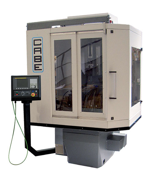
Slotting Machine
TTF1 CNC
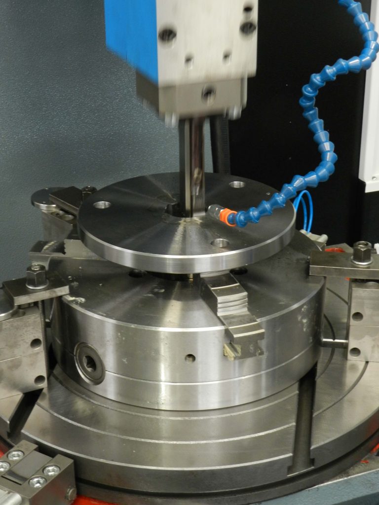
Slotting Machine with one controlled axis and rod-crank system for the movement of the tool.
A modern and technological range characterized by 1 controlled axis and various models with different strokes of the tools. Each model is available with rectangular or swivel table.
The Fanuc 0i-MF control with intuitive graphical and customized interface allows the programming of gradual incremental feeds.
Slotting Machine
TTF1 CNC
Slotting Machine with one controlled axis and rod-crank system for the movement of the tool.
A modern and technological range characterized by 1 controlled axis and various models with different strokes of the tools. Each model is available with rectangular or swivel table.
The Fanuc 0i-MF control with intuitive graphical and customized interface allows the programming of gradual incremental feeds.
Highlights

CAST IRON BODY
The monolithic structure made of cast iron ensures precision cutting with vibration absorption during machining.

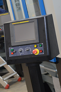
FANUC CONTROL
The control panel and the motors are FANUC. Cabe develops internally all the software programs in collaboration with Fanuc.

BRUSHLESS MOTORS
The controlled axis is moved by brushless motors and managed directly by the Fanuc control.
Technical Characteristics
- Monolithic structure made of cast iron to ensure precision cutting with vibration absorption during machining.
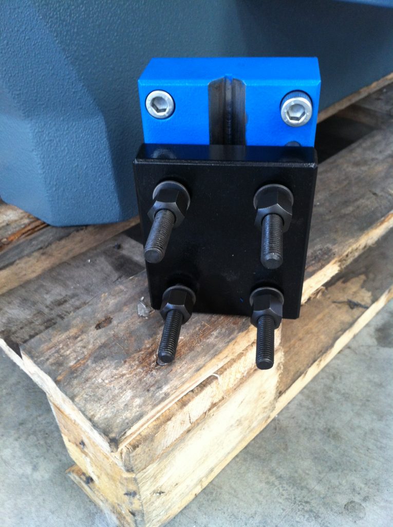
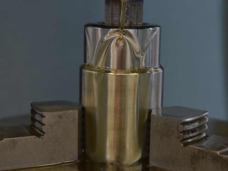
- Universal tool holder “V” shape.
- Automatic disconnection of the tool during ascent phase.
- Minimal lubrication system of the tools (en- tire oil available on demand)
- Tilting head +/- 20°.
- The main slide is driven by a self-braking three-phase asynchronous motor.
- The controlled axes are moved by brushless motors and managed directly by the control.
- The main screw is a preloaded recirculating ballscrew.
- FANUC Control.
- Practical and removable chip collection tank, located below the table.
- Work area illuminated and protected by safety guards with block microswitch.
- Head characterized by linear guides.
- Sliding guides rectified and lubricated with automatic pump, managed by the control.
- CE certification.
- Tool holder with high repeatability that guarantees that the tools are always at the centre of the hole; designed for Cabe Tools.
- Displaying of the manual axes.
- Displaying of the manual swivel-table.
- Tower lamp signalling the machine status.
- Automatic chip conveyor.
- Hand wheel for manual movement.
TTF1 WITH RECTANGULAR TABLE
| CHARACTERISTICS | DIMENSIONS | ||||
|---|---|---|---|---|---|
| 250 | 350 | 450 P | 520 P | ||
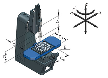
| Settable stroke of tool [mm] | A | 0-250 | 0-350 | 0-450 | 0-520 |
| Adjustable distance between Ram & Table [mm] | B | 115 | 260 | 370 | 550 |
| Distance between tool-holder & column [mm] | C | 410 | 470 | 550 | 550 |
| Distance between underhead / rec. table [mm] | D | 390 | 470 | 670 | 870 |
| Size of rectangular partholder table X x Y [mm] | 300×450 | 500×700 | 500×1000 | 500×1000 | |
| Table central hole [mm] | E | Ø 80 | Ø 100 | Ø 110 | Ø 110 |
| Strokes of the table [mm] | Cx x Cy | 310×270 | 410×320 | 580×460 | 580×460 |
| Motor/brake power [kW] | 3 | 5,5 | 7,5 | 11 | |
| Adjustment of the number of strokes [strokes/ min.] | 10-90 | 5-60 | 5-55 | 5-55 | |
| Max workpiece length for machining [mm] | Ø 60×700 | Ø 95×1200 | Ø 100×1350 | Ø 100×1550 | |
| Power Supply | 400V-50Hz-3phase | 400V-50Hz-3phase | 400V-50Hz-3phase | 400V-50Hz-3phase | |
| Approx. net weight [Kg] | 1300 | 2200 | 3200 | 3600 | |
| Machine dimensions LxPxH [mm] | 1500x2000x2100 | 2000x2050x2620 | 2500x2400x3249 | 2500x2400x3662 |
TTF1 WITH SWIVEL TABLE
| CHARACTERISTICS | DIMENSIONS | ||||
|---|---|---|---|---|---|
| 250 | 350 | 450 P | 520 P | ||
| Settable stroke of tool [mm] | A | 0-250 | 0-350 | 0-450 | 0-520 |
| Adjustable distance between Ram & Table [mm] | B | 155 | 260 | 370 | 550 |
| Distance between tool-holder & column [mm] | C | 410 | 470 | 550 | 550 |
| Space between head & swivel table [mm] | D | 335 | 420 | 610 | 810 |
| Center table hole diameter [mm] | Ø 350 | Ø 500 | Ø 600 | Ø 600 | |
| Table central hole [mm] | E | Ø 80 | Ø 100 | Ø 110 | Ø 110 |
| Strokes of the table [mm] | Cx x Cy | 310×270 | 410×320 | 580×460 | 580×460 |
| Motor/brake power [kW] | 3 | 5.5 | 7.5 | 11 | |
| Adjustment of the number of strokes [strokes/ min.] | 10-90 | 5-60 | 5-55 | 5-55 | |
| Max workpiece length for machining [mm] | Ø 60×700 | Ø 95×1200 | Ø 110×1350 | Ø 110×1550 | |
| Power Supply | 400V-50Hz-3phase | 400V-50Hz-3phase | 400V-50Hz-3phase | 400V-50Hz-3phase | |
| Approx. net weight [Kg] | 1300 | 2200 | 3200 | 3600 | |
| Machine dimensions LxPxH [mm] | 1500x2000x2100 | 2000x2050x2620 | 2500x2400x3249 | 2500x2400x3662 |
To allow further stability, the “Power” (“P”) models are characterized by an even more massive structure.